LC79 Intake Manifold
Overview
3D Printing is a gimmick? Think again.
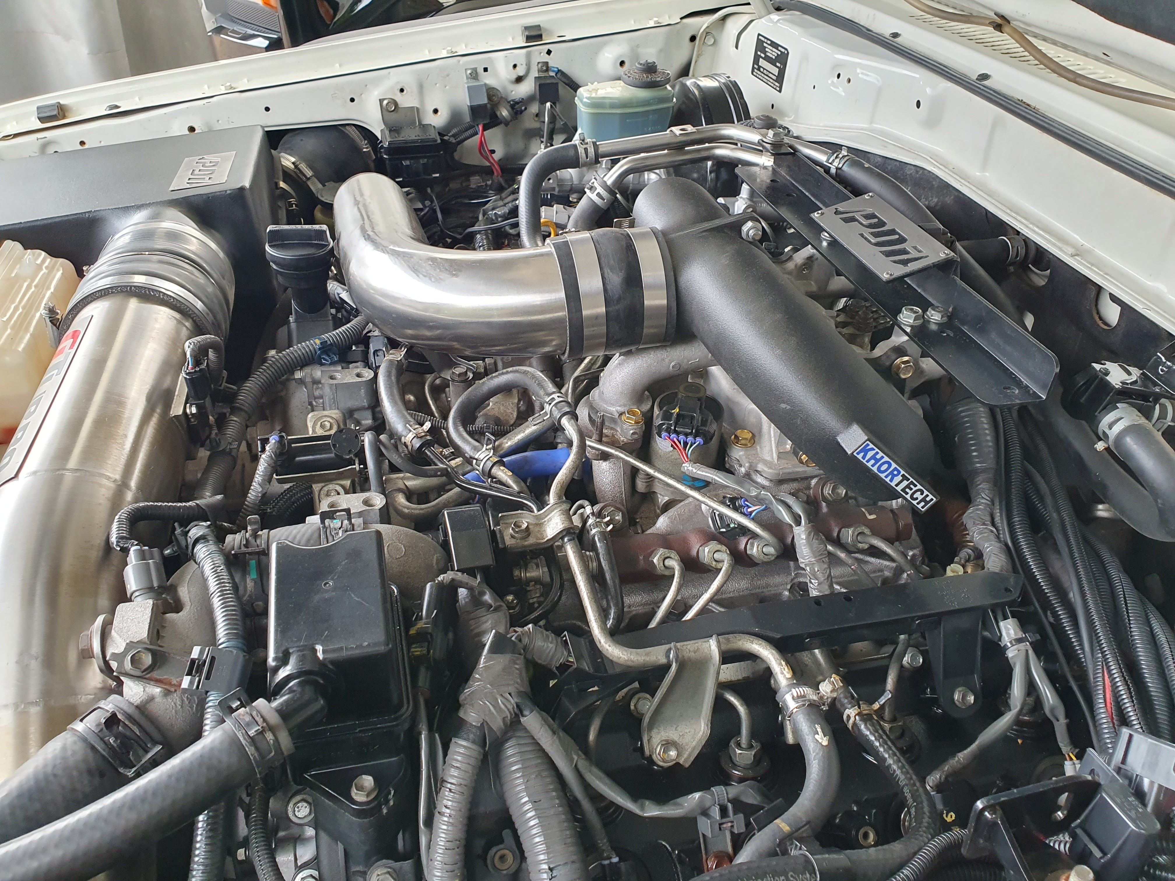
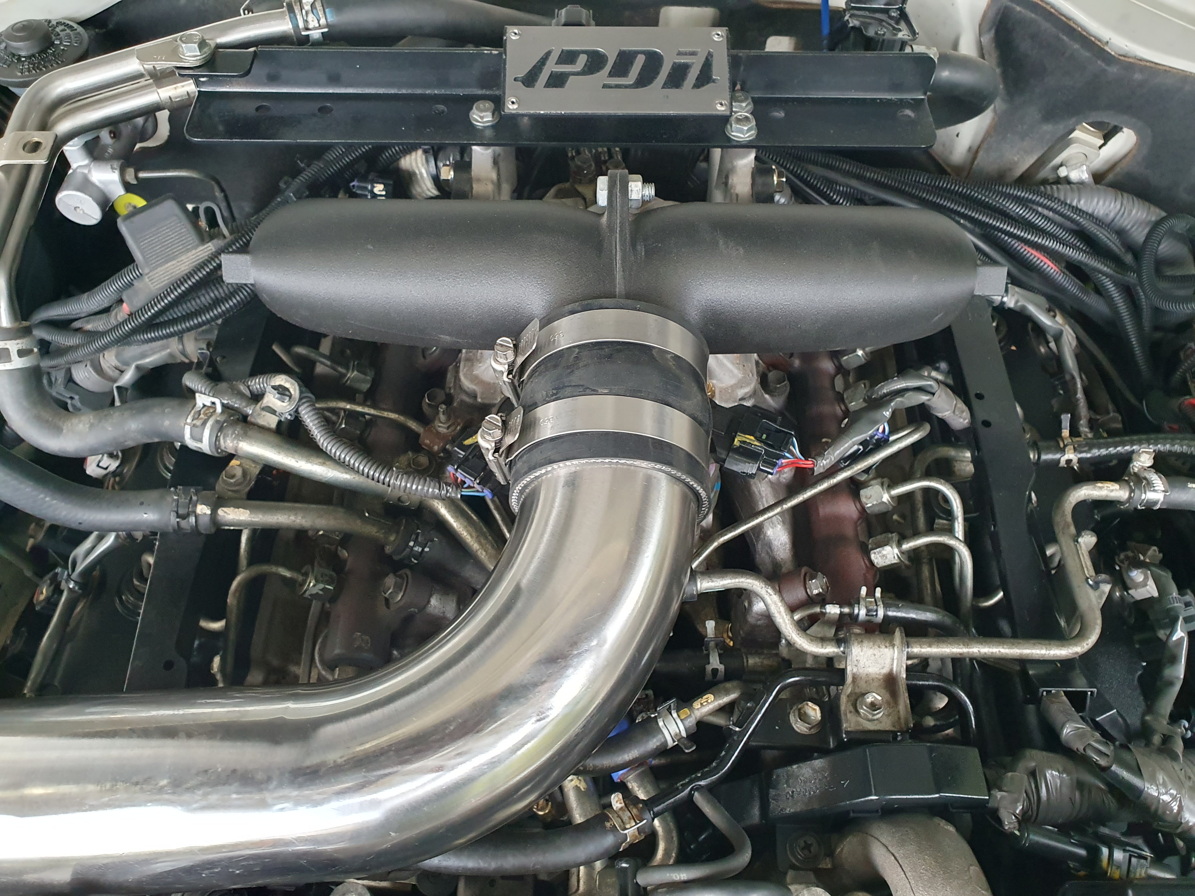
We were presented with a LC79 Lancruiser ute with a 1VD-FTV V8 engine heavily modified by GTurbo in Western Australia. The vehicle had the EGR and throttle bodies deleted as well as a custom manifold top hat and front mount intercooler and pipework.
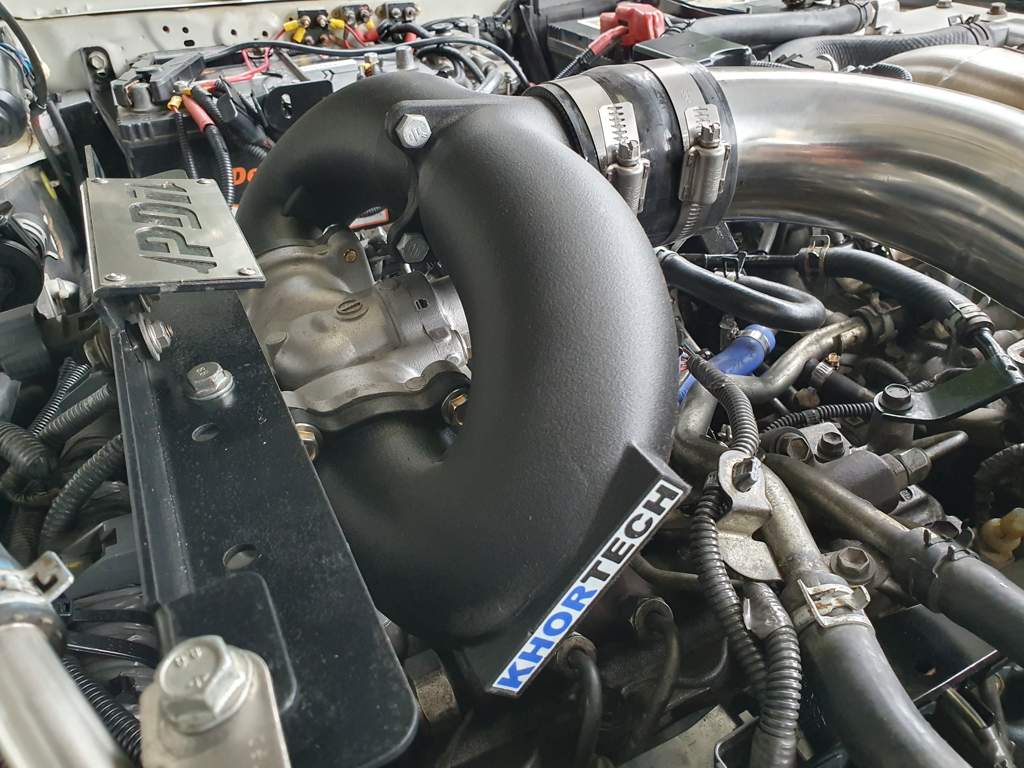
The vehicle was required to have the EGR re-fitted temporarily to pass inspection but the top hat didn’t have provisions for the required EGR plumbing. The solutions was to re-fit the standard top hat but this required an interface between the single front entry 3 inch intercooler piping and the dual side entry throttle body flanges.
Technical Approach
Cost and time constraints as well as advances in modern engineering filaments meant 3D printing was the optimal solution. We selected a filament used extensively by McLaren and Formula One teams (PAHT-CF) due to its high strength, heat and chemical resistance.
PAHT-CF (Polyamide High Temperature - Carbon Fiber) is an engineering-grade 3D printing filament that combines a high-performance polyamide base with carbon fiber reinforcement. This material offers exceptional mechanical properties including high tensile strength, excellent dimensional stability, and superior heat resistance up to 150°C continuous use. The carbon fiber reinforcement provides increased stiffness and reduced warping compared to standard nylons, while maintaining excellent chemical resistance to fuels, oils, and automotive fluids. These properties make PAHT-CF ideal for demanding automotive applications where traditional plastics would fail, allowing for rapid prototyping and production of functional parts that can withstand the harsh under-hood environment.
Excecution
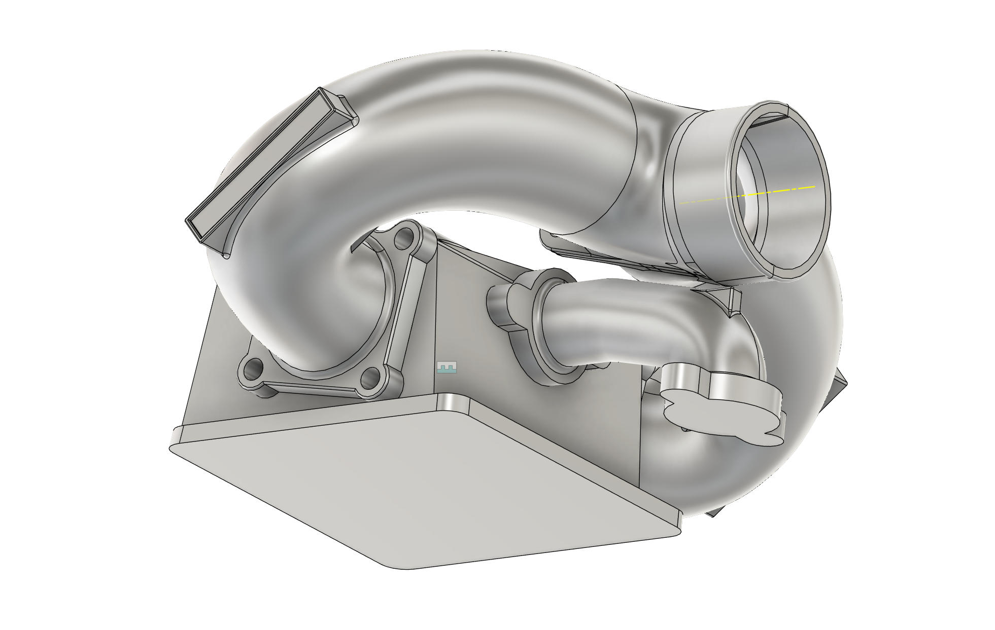
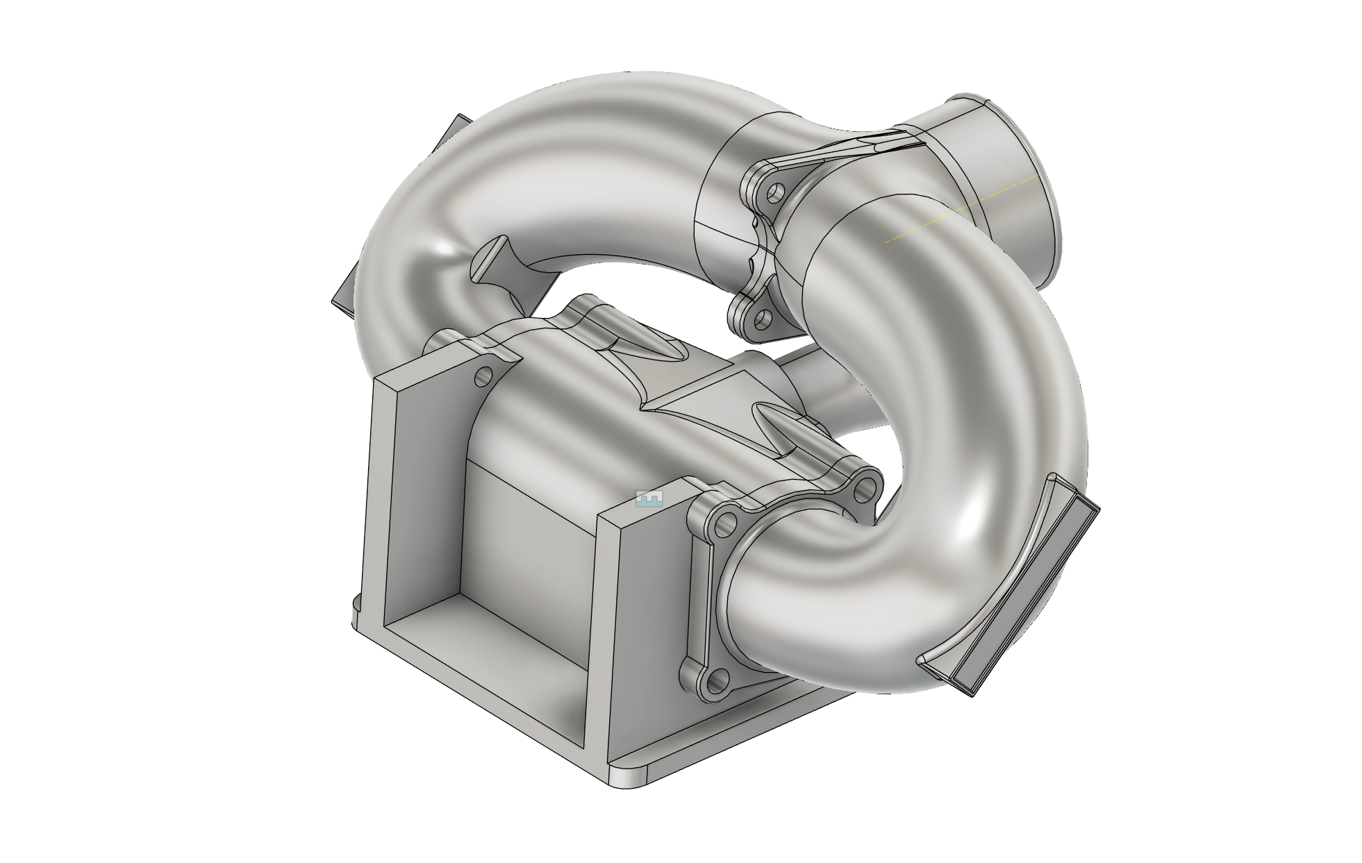
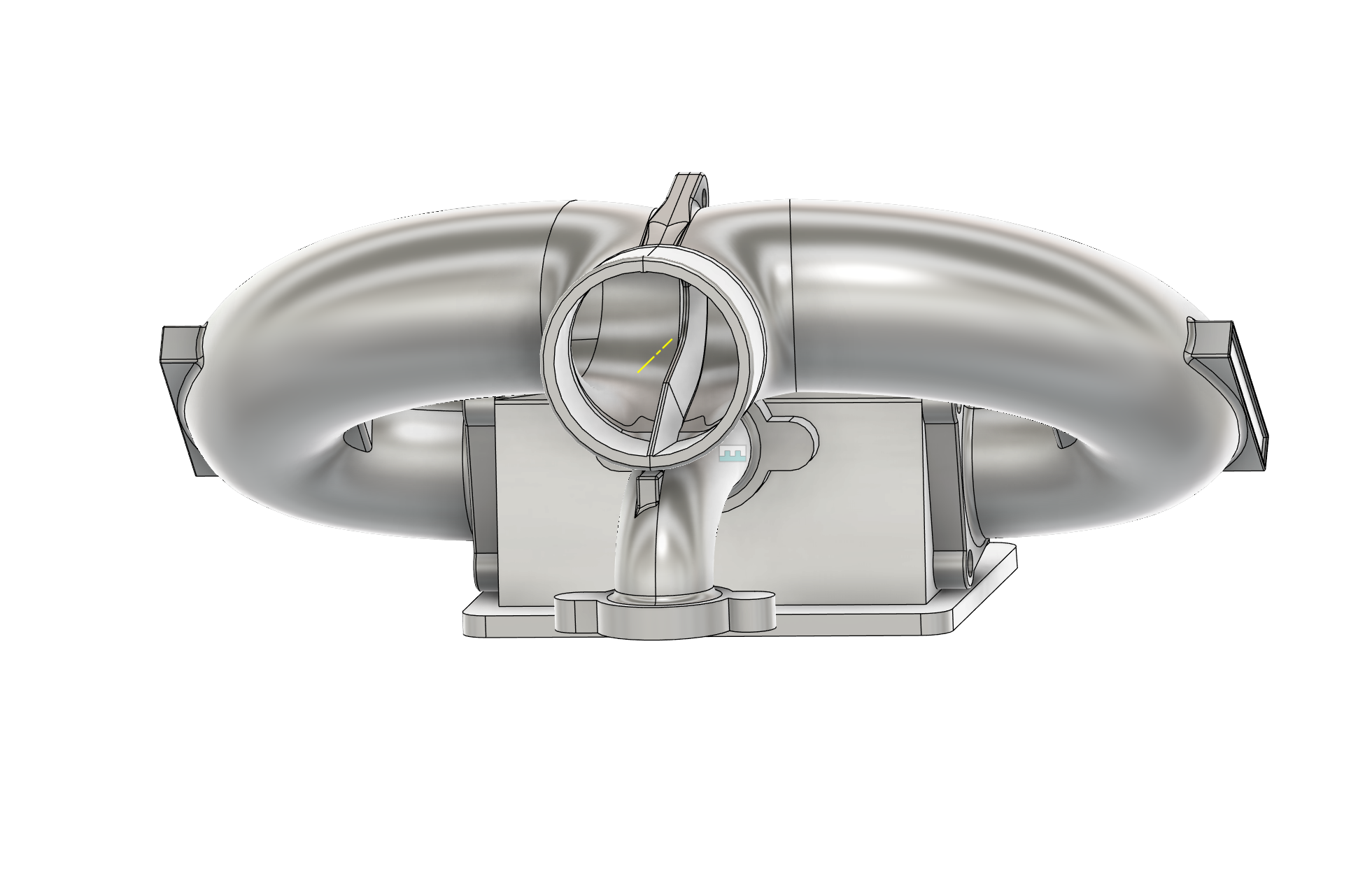
The design process began with meticulous measurements of the throttle body flanges, intercooler piping, and surrounding components to establish their relative position and precise dimensional constraints. The tight space and non-coplanar relationship between the intercooler pipe and throttle body flanges presented a significant challenge to optimising the flow path but it would ultimately still exceed the requirements. Using powerful CAD software, we carefully balanced airflow efficiency with the geometric realities of the installation. The final design prioritized smooth internal transitions, continual wall thickness, reduction of concentrated stresses for structural integrity and accurate flange interfaces for leak-free sealing.
For this proof of concept, the design was cut in half and joined due to the size limitations of our current printer. This joint, although not the most aesthetically pleasing, performed beyond our expectations. Ultimately, the piece would be printed monolithically by one of our trusted partners if progressed to the prototype or production stage, along with other aesthetic and durability enhancements. It has performed flawlessly over a 6 month test period and we look forward to completing destructive testing on it and working toward the next iteration.
Images & Media
Specifications
| Parameter | Value |
|---|---|
| Material | PAHT-CF |
| Dimensions | 390 x 230 x 180 |
| Weight | 596.5 grams |
| Operating Temperature | -40°C to +150°C |
| Lead Time | X days |